



Pharmaceutical powder handling equipment most often fails between transfer and dosing when the powder, containment route and feeder are specified as separate items rather than as one controlled system. A vacuum transfer line may move material successfully but leave a compacted, aerated or segregated feed zone. A dust collector may keep the room cleaner while an open charging point still breaks the intended containment boundary. A dosing device may be correctly calibrated when empty, then drift once its hopper receives powder with a different bulk state. The practical answer is to verify each handoff: source container to transfer, transfer to receiver, receiver to hopper, hopper to feeder, and feeder to the next unit operation.
This article addresses dry-powder handling before blending, tableting, encapsulation or package filling. It is not a substitute for a health-based exposure assessment, a dust-hazard review, a cleaning-validation strategy or an approved site SOP. The applicable configuration depends on the material, batch size, exposure-control need, equipment, utilities and validated process conditions.
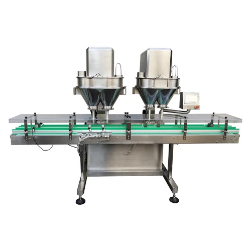
Example downstream dosing equipment. The transfer route, hopper refill behavior and cleaning boundary still require project-specific verification. Image source: SED Pharma automatic auger powder filling machine.
Start with the process question, not a list of machines
"Closed-loop" is useful only when it describes an actual, testable boundary. In a pharmaceutical powder handling system, that boundary can include the source drum or bag, connection method, conveying hose, receiver, filter, discharge valve, intermediate container, feed hopper and dosing device. The path is only as controlled as its least-controlled opening: charging, filter change, sampling, discharge, cleaning or a manual intervention.
That distinction separates this topic from a powder mixer selection. A mixer addresses blend preparation; pharmaceutical powder handling addresses whether the prepared material reaches the next operation without unacceptable loss, contamination opportunity, segregation, dust release or dose disturbance. Likewise, a package filler is not a complete handling system. The existing overview of what a powder filling machine does is a useful downstream reference, but its metering function begins after the incoming powder has already been transferred and conditioned at the hopper.
Where closed-loop transfer, dust control and dosing disconnect
Most symptoms are not root causes. For example, a weight variation trend can originate in feed-hopper level changes, powder de-aeration, segregation during transfer, inconsistent refill timing, bridging, filter resistance or the feeder itself. The table below is a triage tool, not a release decision. Confirm changes through the site's approved assessment and validation process.
| Observed symptom | Possible mechanism | First confirmation test | Controlled next action |
|---|---|---|---|
| Dust appears when charging or disconnecting | The physical containment boundary is open, poorly seated or not balanced with extraction. | Observe the connection sequence and document where dust becomes visible; check seals, clamps and extraction status. | Review the connection design and operating sequence before increasing extraction or changing settings. |
| Transfer rate slows or stops intermittently | Bridging, hose restriction, filter loading, insufficient pickup or an unstable source discharge. | Trend transfer time and receiver level against material lot, hose route, filter condition and source level. | Test one variable at a time using representative material; do not assume vacuum level alone is the cause. |
| Measured output shifts after a hopper refill | Changed bulk state, aeration, head pressure, segregation or a non-repeatable feeder inlet condition. | Compare feed behavior and measured output before, during and after a controlled refill. | Set an evidence-based refill strategy and verify the feeder across its working hopper-level range. |
| Material remains in a receiver or hopper | Wall friction, cohesive powder, unfavorable geometry, air effects or insufficient discharge assistance. | Inspect residue location after a representative discharge; distinguish hold-up from an acceptable operational heel. | Review vessel and outlet geometry, material conditioning and cleaning implications together. |
| Room dust appears controlled, but output still varies | Extraction may capture airborne dust without solving material-flow or feeder-inlet variation. | Separate environmental observations from output-weight and material-flow data. | Treat containment performance and dosing performance as linked but separately verified requirements. |
Dust control is a boundary-and-recovery problem
A filter, dust collector or local extraction point can be part of the solution, but it does not automatically make a powder route closed. Dust control begins with reducing uncontrolled openings and defining how displaced air, fines and retained material are managed. It also requires knowing where the system is intentionally opened for charging, sampling, cleaning, inspection and filter service.
Ask practical questions at each interface. Is the transfer connection mechanically repeatable? What happens to displaced air while the receiver fills? Does the filter-cleaning cycle change the powder condition or discharge pattern? Where can material settle during a stop? How is that residue inspected and cleaned? If the material has a higher exposure-control requirement or presents a dust hazard, these questions must be taken into the formal risk assessment rather than answered by a generic equipment claim.
For example, a vacuum receiver can help move powder to a mixer or feeder, but its suitability depends on the source discharge, hose routing, filtration arrangement, receiver discharge and cleaning plan. Use a relevant V-type mixer with vacuum-feeding capability as a product-level discussion point, not as proof that every powder can be transferred or contained in the same way.
Dosing starts at the feeder inlet
Dosing performance is often treated as a feature of the auger, screw, valve or scale. In practice, the metering device only sees the material state presented to it. Changes in bulk density, particle-size distribution, moisture response, electrostatic behavior, entrained air, hopper level and refill pattern can all change that inlet condition. A feeder can therefore pass a static check and still show a process trend after repeated transfer-and-refill cycles.
A robust test plan measures output over the actual operating sequence, not only a short run after setup. It should include startup, normal running, minimum and maximum intended hopper levels, at least one representative refill, normal stops and restart where relevant. Use the approved sampling and analytical approach for the product; the purpose is to show whether the transfer route changes the material state or the output behavior, not merely whether a nominal setpoint can be entered.
When container filling is the destination, an automatic auger powder filling machine may provide the dosing function, but the upstream hopper, refill logic and powder route remain part of the performance question. For wet-granulated products, the upstream handoffs deserve the same attention; see the related article on wet granulation equipment from high-shear to fluid-bed handoff.
Illustrative measurement layout for output before, during and after hopper refill A schematic trend line shows stable measured output before refill, a possible shift during refill, and a separate post-refill stabilization measurement period. It is not product data or an acceptance limit. Measured output Time / sample sequence Before refill During refill After stabilization Establish baseline Record refill event Confirm recoveryIllustrative measurement layout only. This is not product data, a typical performance curve or an acceptance criterion. Plot the actual measured output and identify the refill start/end, hopper level and any setting change. A shift should trigger investigation of the feeder inlet and transfer conditions before changing the metering setting.
A six-step verification path for powder handling systems
- Draw the real material path. Include source container, connection type, transfer line, receiver, filter, discharge, hold vessel, feeder and destination. Add operator interventions and cleaning breaks.
- Define the material evidence. Record the attributes known to affect transfer and feeding, such as flow behavior, bulk condition, particle characteristics, moisture sensitivity and electrostatic observations. Do not substitute a generic powder description for representative material data.
- Set containment and cleaning boundaries. Identify openings, displaced-air paths, filter service, dust-recovery route, residue locations and the proposed cleaning method. Escalate exposure-control or dust-hazard questions to the responsible site assessment.
- Test the transfer itself. Observe source discharge, line behavior, receiver fill and discharge across representative cycles. Capture interruptions, residue and visible release points rather than only average transfer time.
- Test the feeder through refill. Correlate measured output with hopper level and refill events. If output changes, investigate the inlet condition before changing a feeder setting.
- Document the decision and ownership. State what was demonstrated, what remains to be verified, the operating limits, cleaning responsibility, extraction interface and acceptance authority. Changes that affect product quality or validation status require the approved change-control path.
Minimal record data set for a transfer-to-dosing verification
A trial does not need a generic "pass/fail" note. Record enough evidence to compare the material state, transfer event and output response. The exact data fields, sampling plan, analytical method and acceptance criteria remain product- and site-specific.
| Record group | Minimum information to capture | Why it matters |
|---|---|---|
| Material and batch context | Material/batch identifier, formulation status, relevant flow or bulk-condition observations, source-container condition. | Separates a powder-change effect from an equipment-change effect. |
| Equipment configuration | Equipment and tooling IDs, transfer route, receiver/filter state, feeder setup, active recipe or approved settings. | Makes the result traceable to the actual configuration tested. |
| Transfer and refill event | Start/end times, source and hopper level where available, interruptions, connection or filter intervention, visible residue or release observation. | Links output behavior to the event that may have altered inlet conditions. |
| Output evidence | Sample sequence before/during/after refill, measured output, test method, repeat observations and any rejected or excluded result with rationale. | Shows whether the observed shift is repeatable and representative. |
| Decision and escalation | Reviewer, deviation/change-control reference where applicable, conclusion, next test or approved corrective action. | Preserves decision ownership; it is not a substitute for the site quality record. |
Evidence basis for the verification approach
The logic above is deliberately evidence-led rather than a fixed setting recommendation. FDA's Process Validation: General Principles and Practices describes a sampling plan in terms of sampling points, number of samples and frequency, and emphasizes that samples must represent the batch. Its cGMP production and process-controls Q&A also notes that powder-thief sampling can disturb the powder bed and introduce segregation or other sampling error. That is why an apparent in-vessel result should not be treated as proof of downstream transfer and feeding performance.
ICH Q8(R2) frames the relevant engineering question: identify through prior knowledge, experimentation and risk assessment the material attributes and process parameters that can affect critical quality attributes, then establish a suitable control strategy. The record set and six-step path are a practical way to structure that investigation; they do not establish a universal validation protocol or acceptance limit.
What to include in an early equipment or URS discussion
Useful requests for bulk powder handling equipment describe the process instead of only naming a machine. Provide the dosage form, powder or granule status, batch range, source and destination, desired throughput, container formats, known flow or dust observations, cleaning/changeover expectations, available utilities and the intended level of enclosure. Identify whether the project is a new line, an upgrade or a connection between existing equipment, because the mechanical, electrical and dust-extraction interfaces can determine the viable route.
SED Pharma can use that information to frame an initial equipment discussion around the material path: which handoffs need closer review, which items may need trial evidence, and where the buyer's facility or validation team needs to retain design decisions. This is more useful than choosing a conveyor, receiver or filler independently and discovering interface gaps during installation.
Frequently asked questions
Is vacuum transfer always the best choice for pharmaceutical powder handling?
No. It can be appropriate for some powder routes, but suitability depends on material behavior, transfer distance, source and receiver design, containment needs, cleaning method and the downstream process. Test representative material and assess the complete path.
Does dust extraction solve containment?
No. Extraction can manage airborne dust, but containment also depends on the physical boundary, connection method, operating sequence, cleaning and maintenance tasks. A system should be assessed at its normal openings and interventions.
Why can dosing change after a hopper refill?
The refill can change powder aeration, packing, segregation or the pressure and material level at the feeder inlet. Verify output before, during and after representative refills rather than assuming the metering device alone is at fault.
What should be tested before a handling system is finalized?
At minimum, test the complete intended transfer path with representative material, including normal discharge, refill, stop/restart, residue observation, dust-control interfaces and downstream dosing behavior. The exact protocol belongs in the approved project and quality framework.
Review your powder path before selecting individual equipment
Send SED Pharma your material description, source and destination equipment, batch or throughput target, known dust or flow observations, current transfer route and required cleaning/containment conditions. We can help identify the handoffs that need trial evidence and the information gaps to close before an equipment inquiry.
Request a technical review Explore SED Pharma